
This is a walkthrough of flashing a Sonoff Basic R2 device with the Tasmota firmware so that it can connect to an MQTT broker.
I decided to write this because I wanted an easy way to automate my Christmas lights through Home Assistant. Doing this for the first time offered many different paths and the internet is full of a bunch of tutorials. Mainly I wanted to put together a clear end to end of everything needed and how to do it using macOS. All setup and screenshots will be done using macOS Catalina. The one assumption made is that you’ve already got an MQTT broker setup.
Hardware used:
Software used:
Start with the Software
Download Tasmota
You can download the latest version of Tasmota from the releases page on Github. The current version as of writing this is v7.1.2. Scroll down through the list and download the file named tasmota.bin towards the end of the list of files.
Note: There are others you can use most of which are in various different languages. An explanation of the different versions is on the release page if you are interested. Once downloaded set that to the side for now.
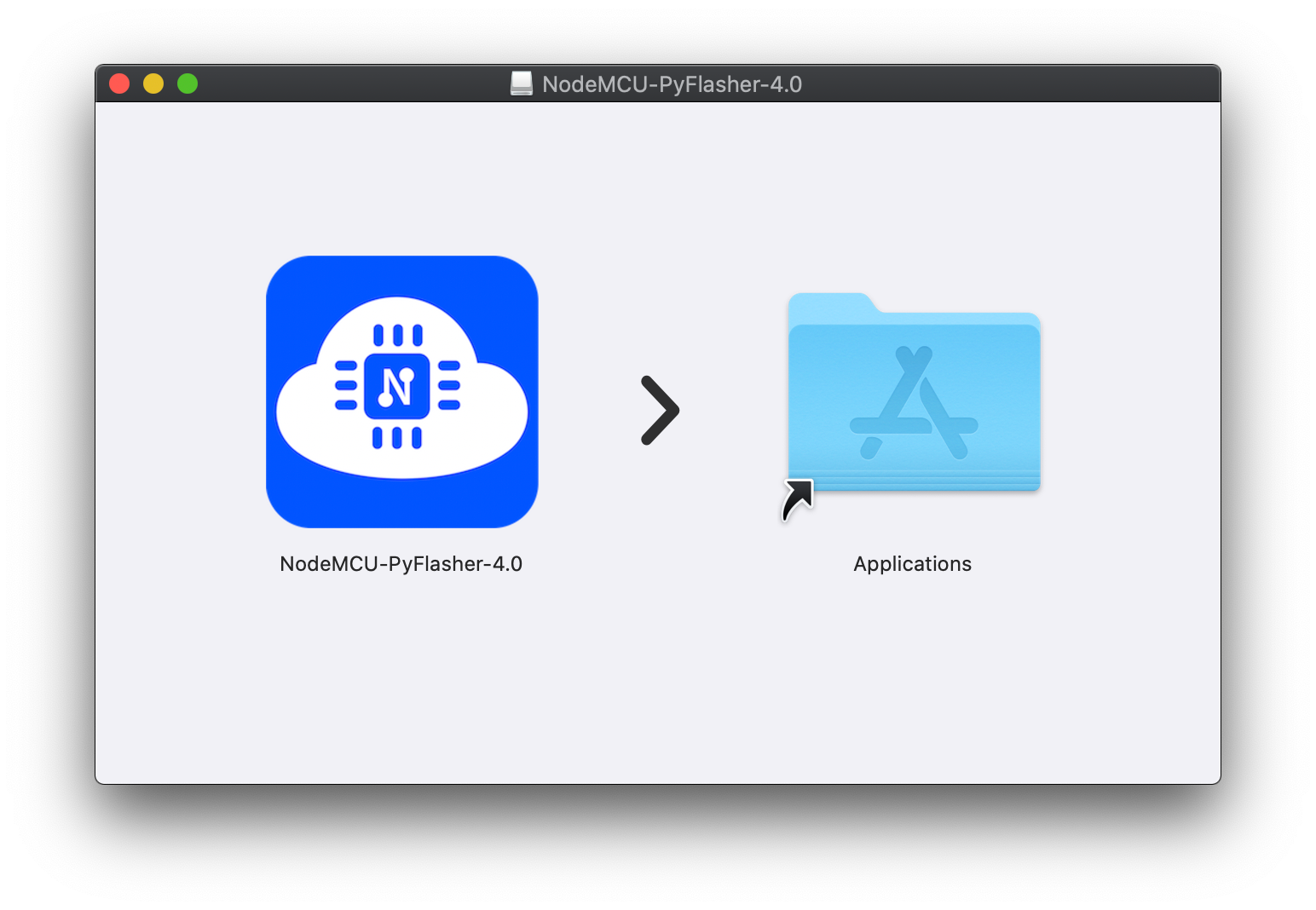
Let’s download and install PyFlasher.
Here you will find the releases page on Github. Go ahead and grab the latest release, which currently is V4.0.
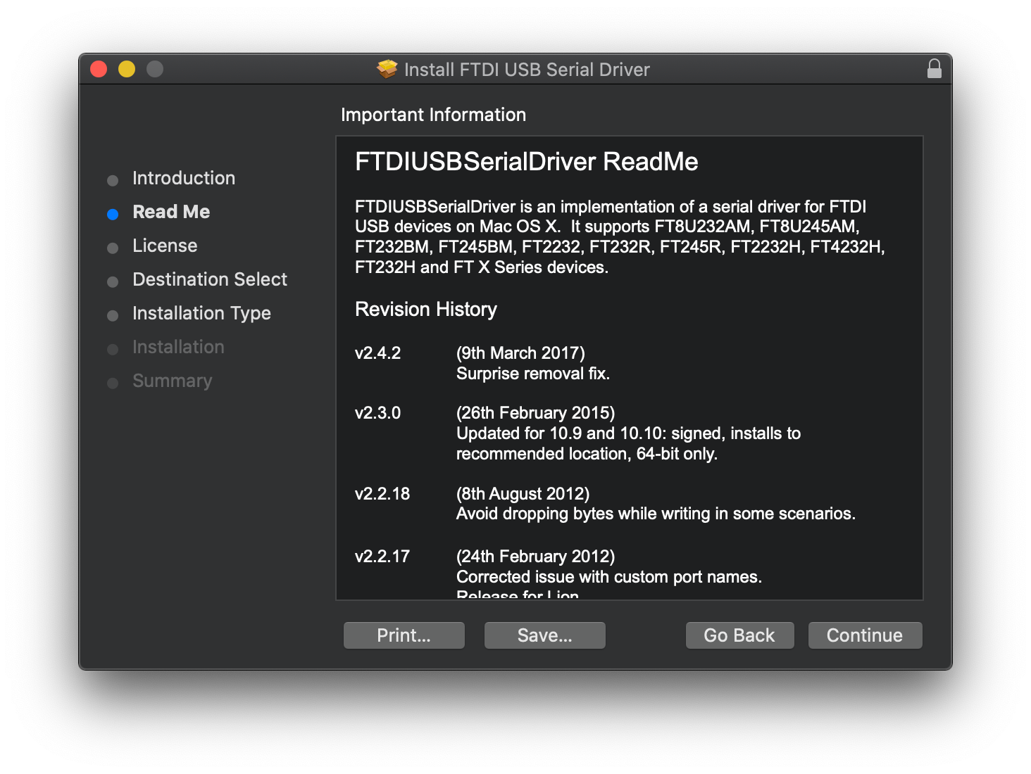
Next download the driver for the USB Serial Adapter from FTDI.
Be sure to pick the right one for the operating system you are on. Installing this on macOS is fairly straight forward with one gotcha. If you're installing the latest Mac driver, its actually signed by Apple.
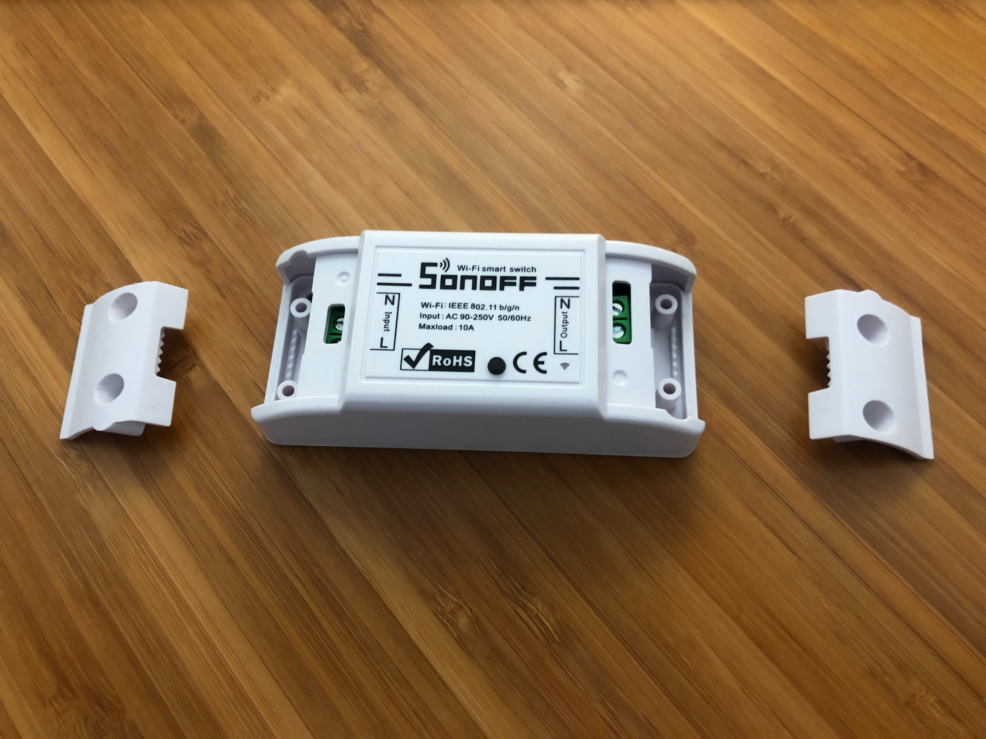
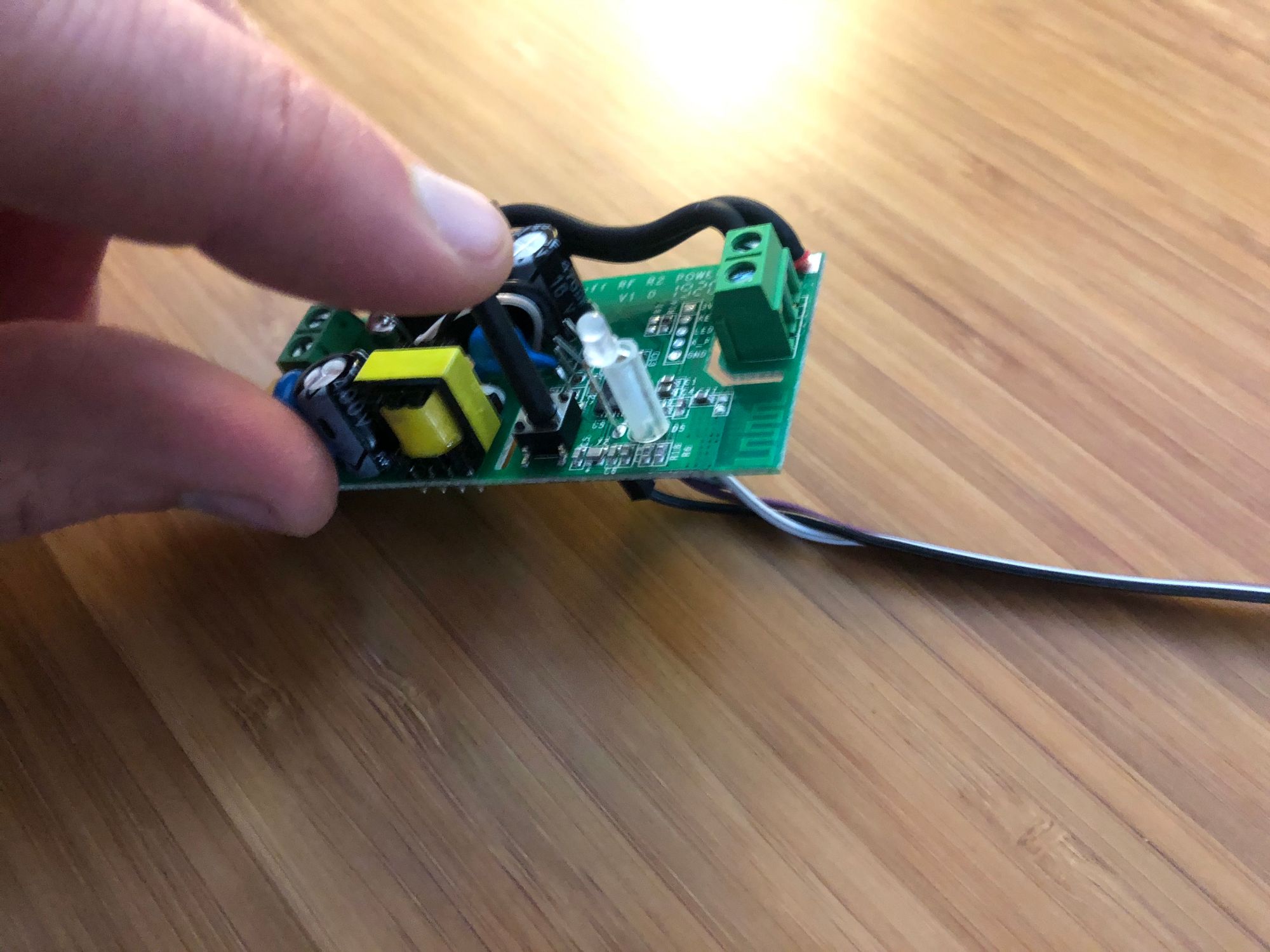
Moving on to prepping the Sonoff R2
Rip everything apart!
First step is to take the caps off the left and the right side of the R2. Then you are going to push the back plastic through the openings on the left and right to detach the top from the bottom.

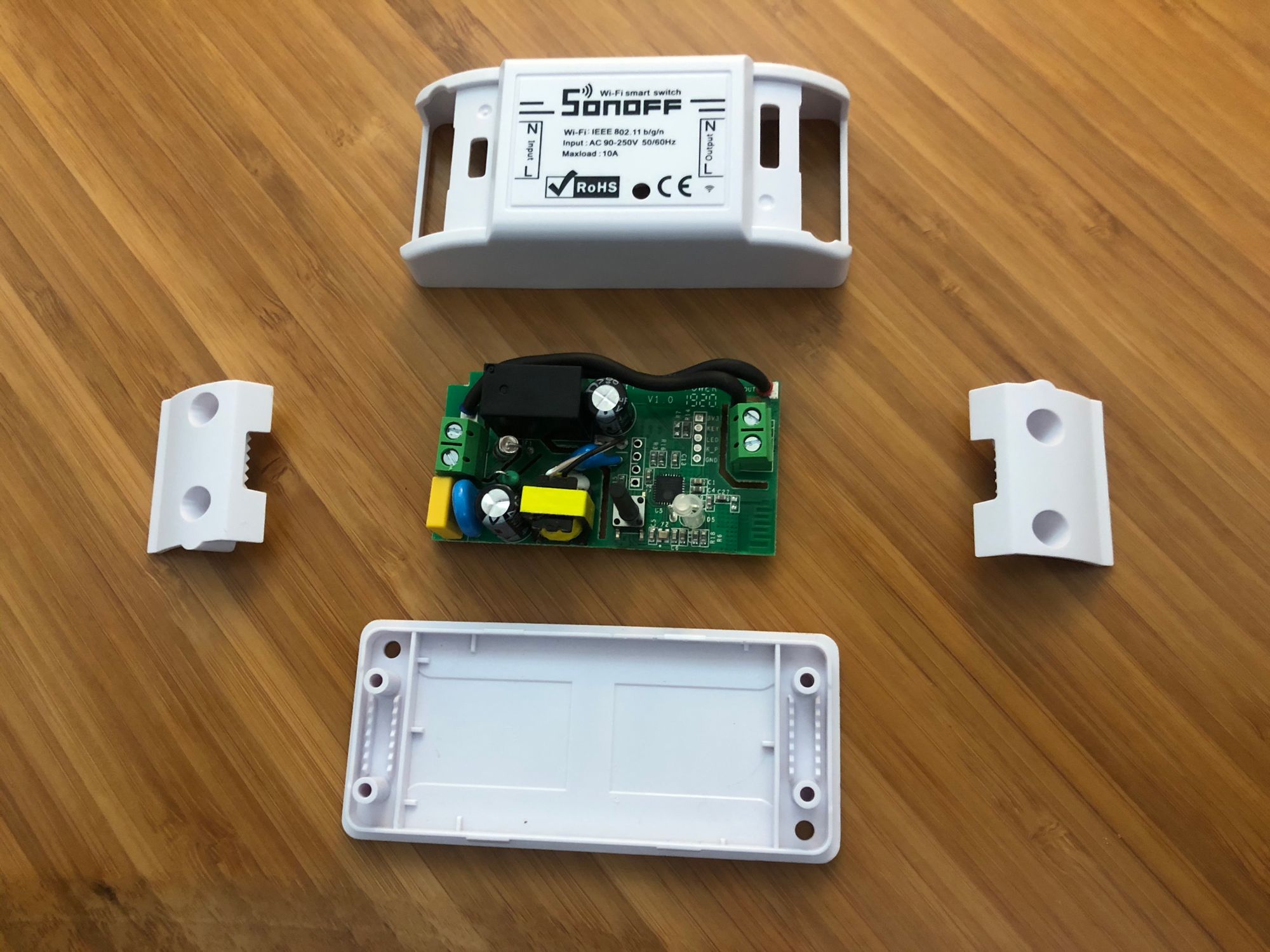
Once thats all done you will just be needing the board and can set everything else off to the side.
Next let’s get the USB to serial adapter ready.
Make sure the little black jumper is connecting the 3v3 pin to the JP pin.
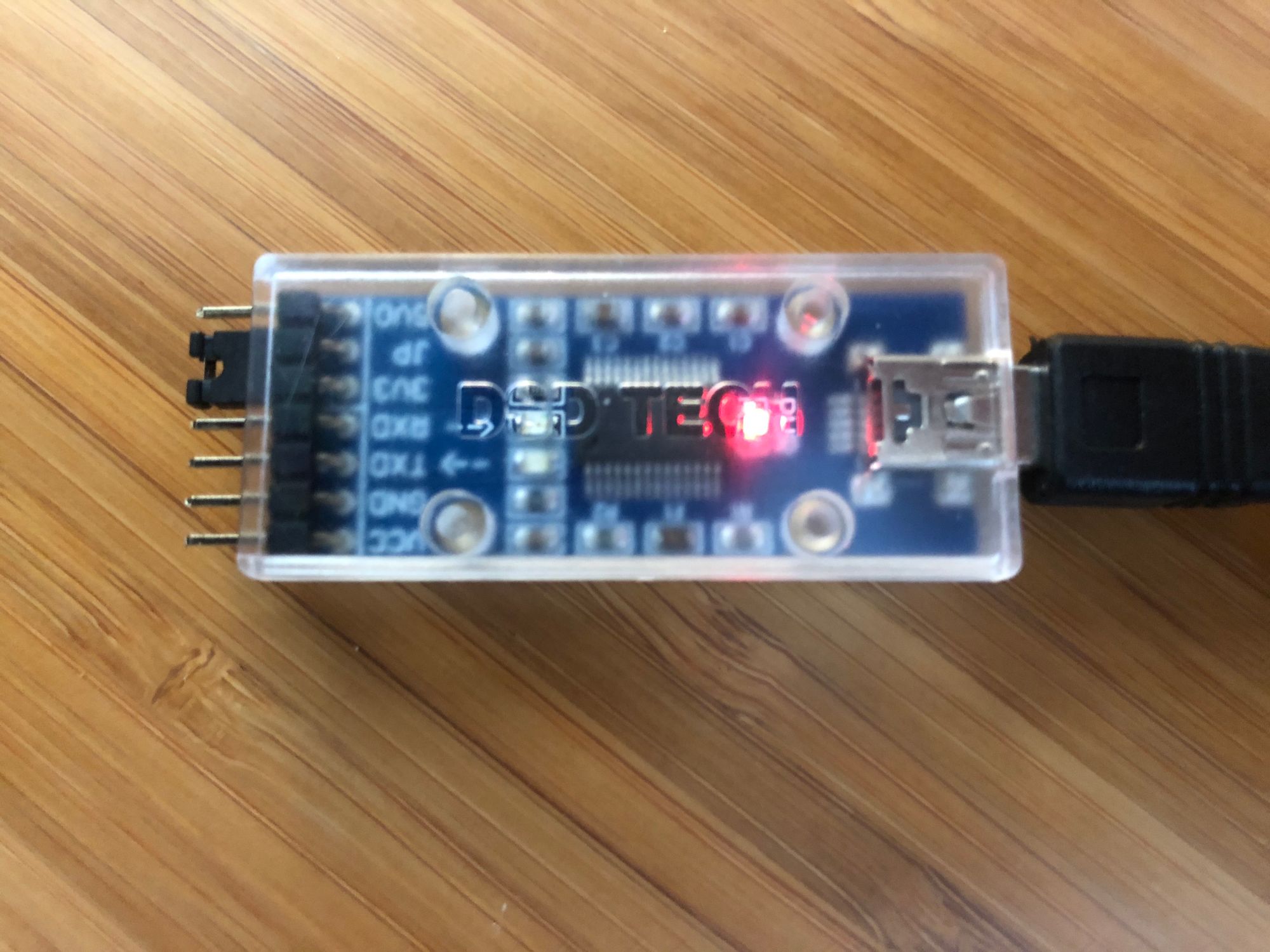
Go ahead and connect your four jumper wires to the remaining pins, which are RXD, TXD, GND, and VCC.
Note: If you don’t have jumper wires and want to use the cable that came with the serial adapter, you could alternatively insert some header pins into the female end of that cable and have the same setup as below.
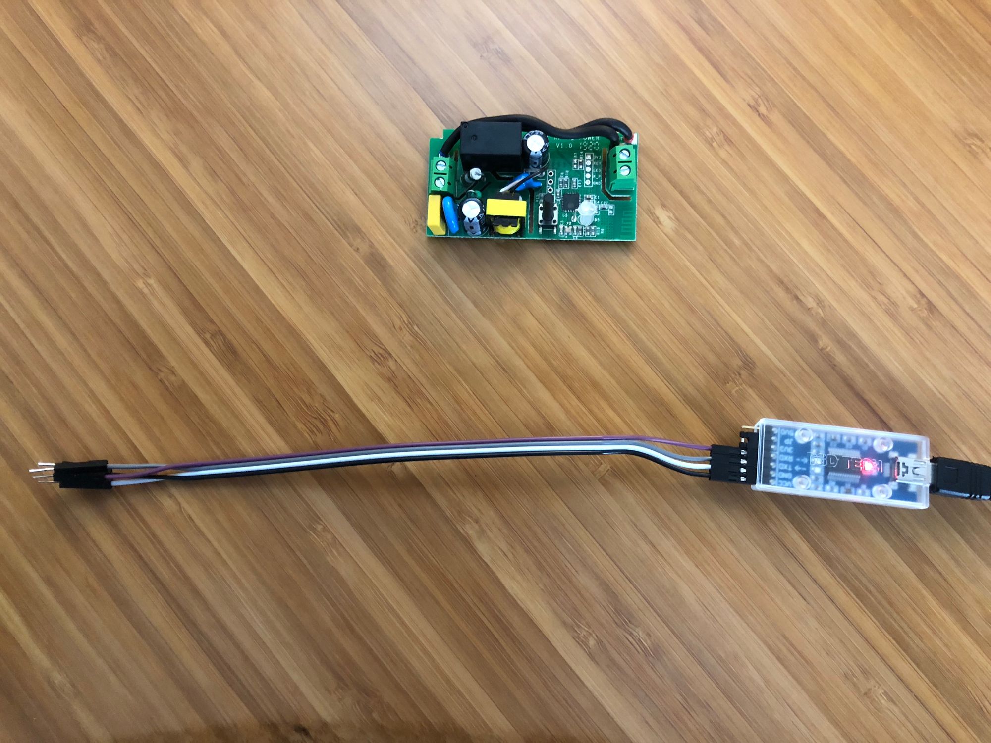
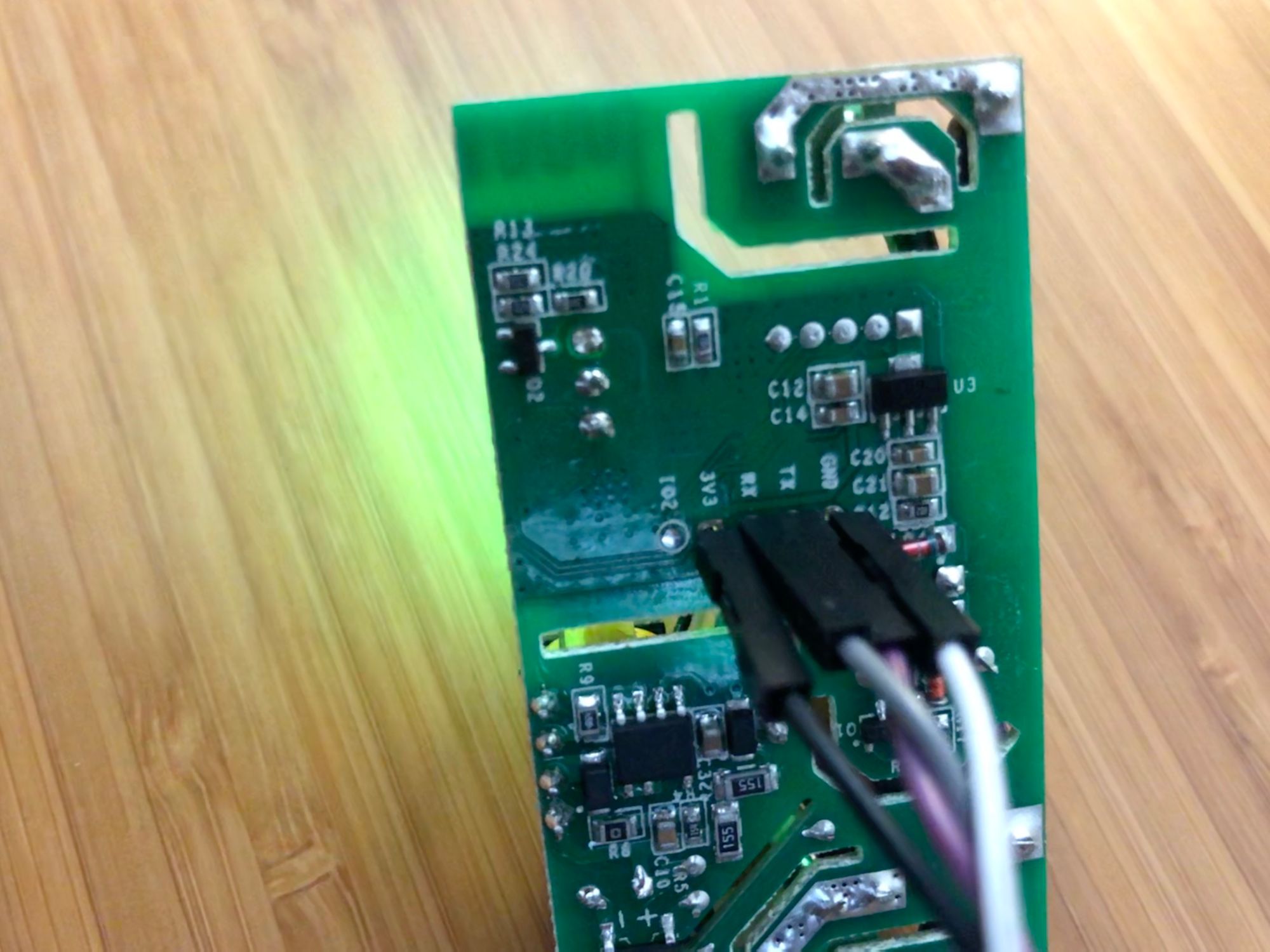
Through the back of the board insert the jumper wire pins into the appropriate holes. They are as follows from the serial adapter to the R2 board.
- GNG → GND
- VCC → 3V3
- TXD → RX
- RXD → TX
If you have the serial adapter plugged in you should see the R2 start to light up and flash green. Now turn the board over and let it rest on the jumper wires.
Flashing time!
Get the R2 into programming mode.
Everything is now set to begin flashing the board.
- Unplug the serial adapter.
- Hold down the tall black button.
- Plug in the serial adapter.
- Release the button.
The ESP8266 chip on the R2 board will now be in programming mode.
Flashing Settings
Open up NodeMCU PyFlasher.
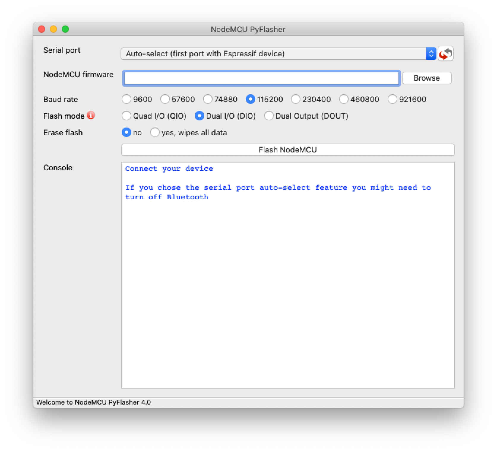
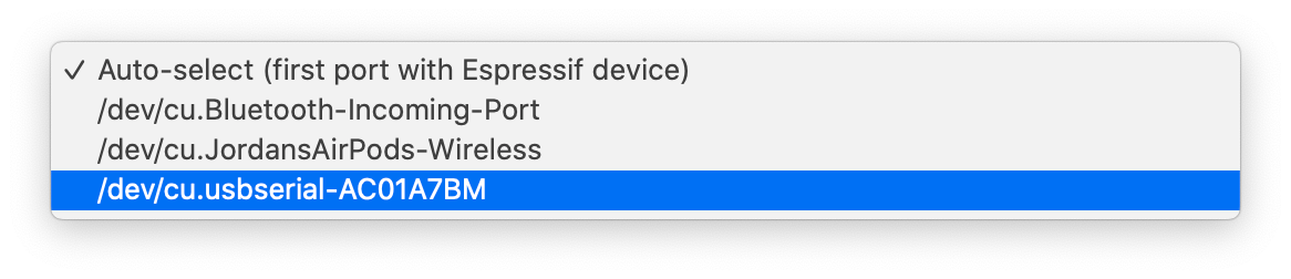
First click the select box for Serial port and look to see that your serial adapter shows up.
Note: If it doesn’t show up try pressing the refresh button to the right. If it still doesn’t show up, try restarting your computer to fix the issue.
Click the browse button and select the location where you downloaded tasmota.bin. Next select the following settings.
- Baud rate: 115200
- Flash mode: Dual Output
- Erase flash: yes
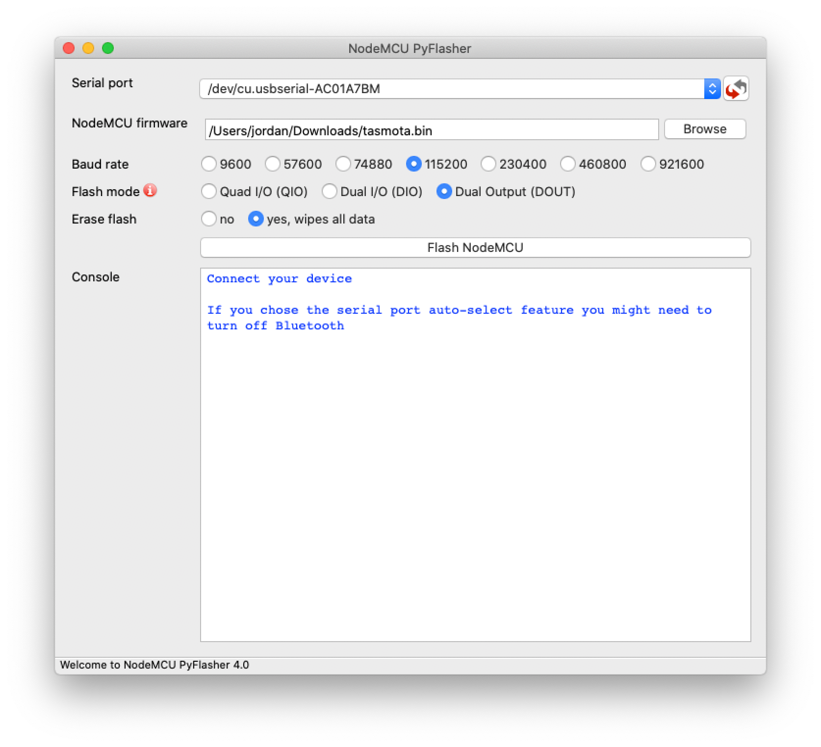
After you have everything set, click the Flash NodeMCU button and wait until it tells you to restart the R2.
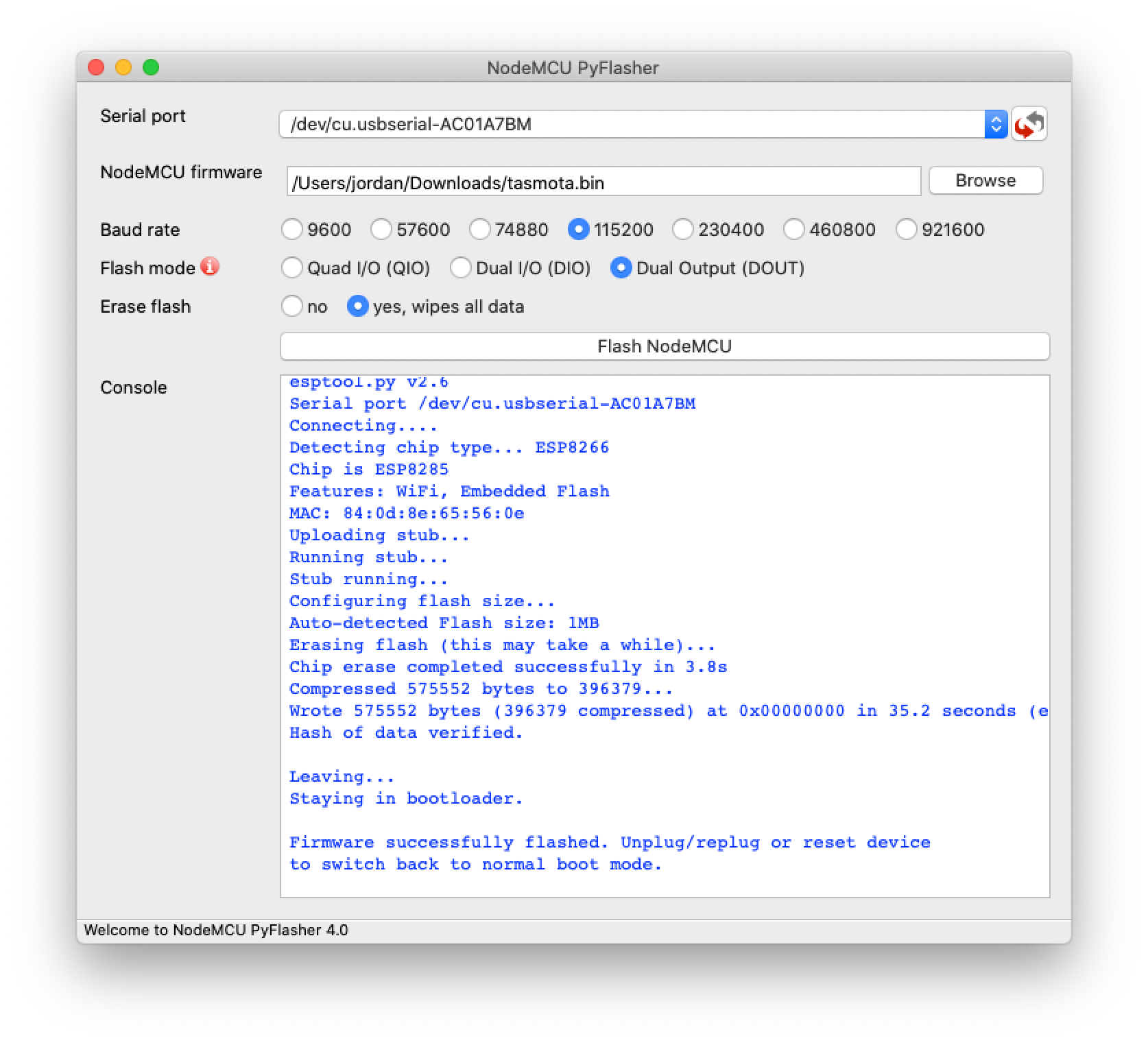
At this point unplug the serial adapter and plug it back in to get the R2 to reboot.
Time to Configure Tasmota
Setup Wifi
Open the wifi settings on your phone. Look for a network being broadcast thats named tasmota-xxxx where xxxx will be some numbers. Tap on that network and you should be prompted with a wifi configuration screen.
Next you can tap the Scan for wifi networks link and then select your network from the list that shows up or directly enter the ssid into the AP1 SSId field. Then enter your password in the AP1 Password field.
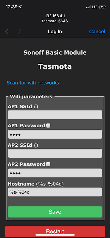
Once you have everything entered tap on the Save button and you will see a screen telling you the R2 is restarting and connecting to your network.
Get the IP Address
After the Sonoff R2 restarts and connects to your network you’ll need to get its ip address.
Note: This can be done through your router or an ip scanner application. It will show up with a hostname of tasmota-xxxx just as it did when we connected to it through wifi in the previous step.
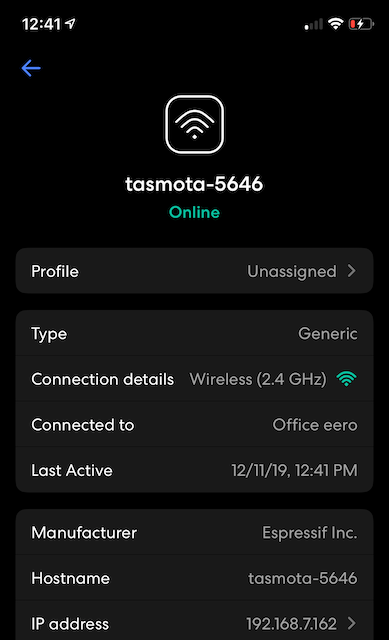
The photo here is an example of what I saw when looking for the newly connected wifi device inside of my Eero App.
Open Tasmota
In your browser put in the ip address and you will see the main page for your R2.
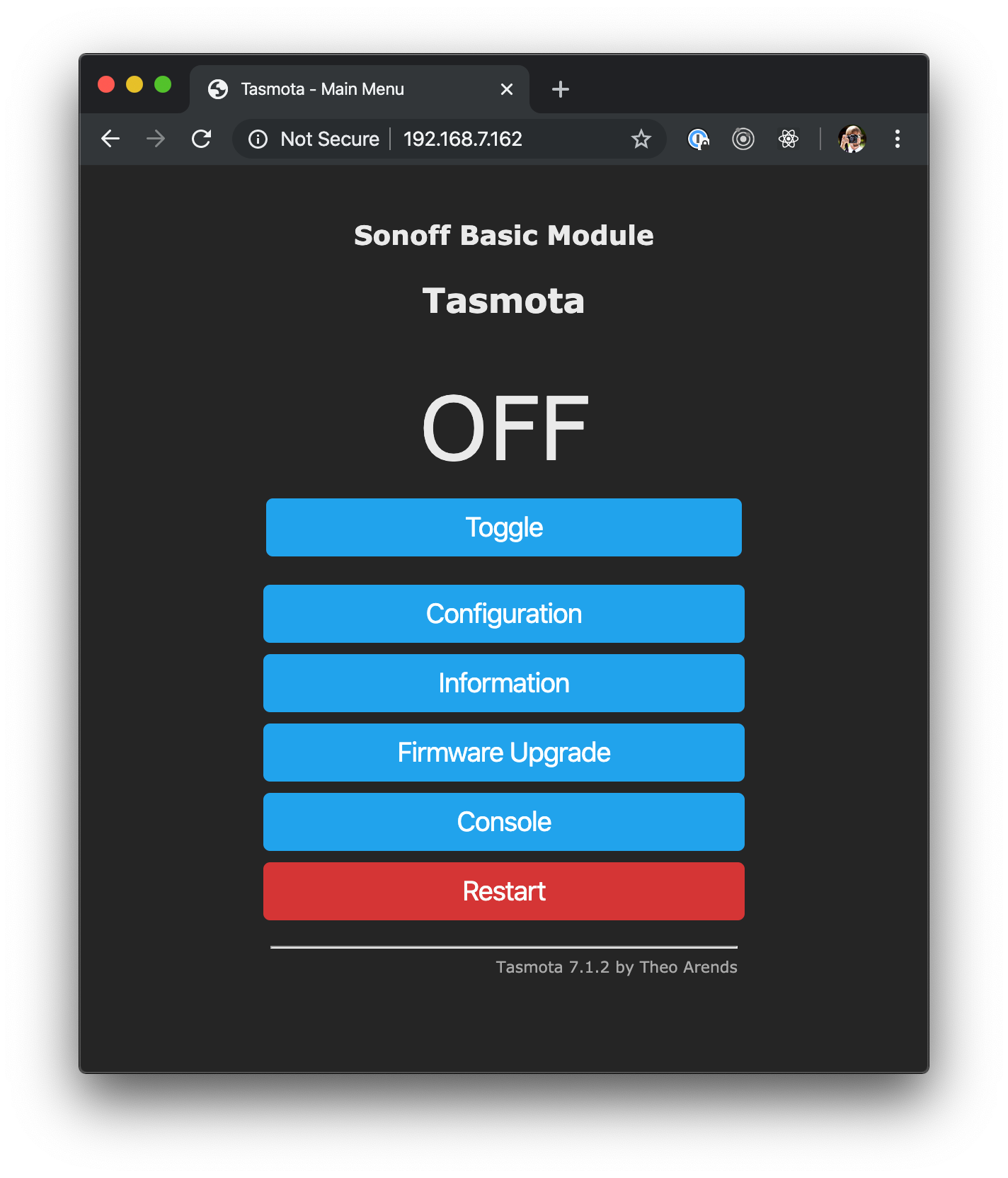
Next click on Configuration and then Configure MQTT and you will see a screen like below.
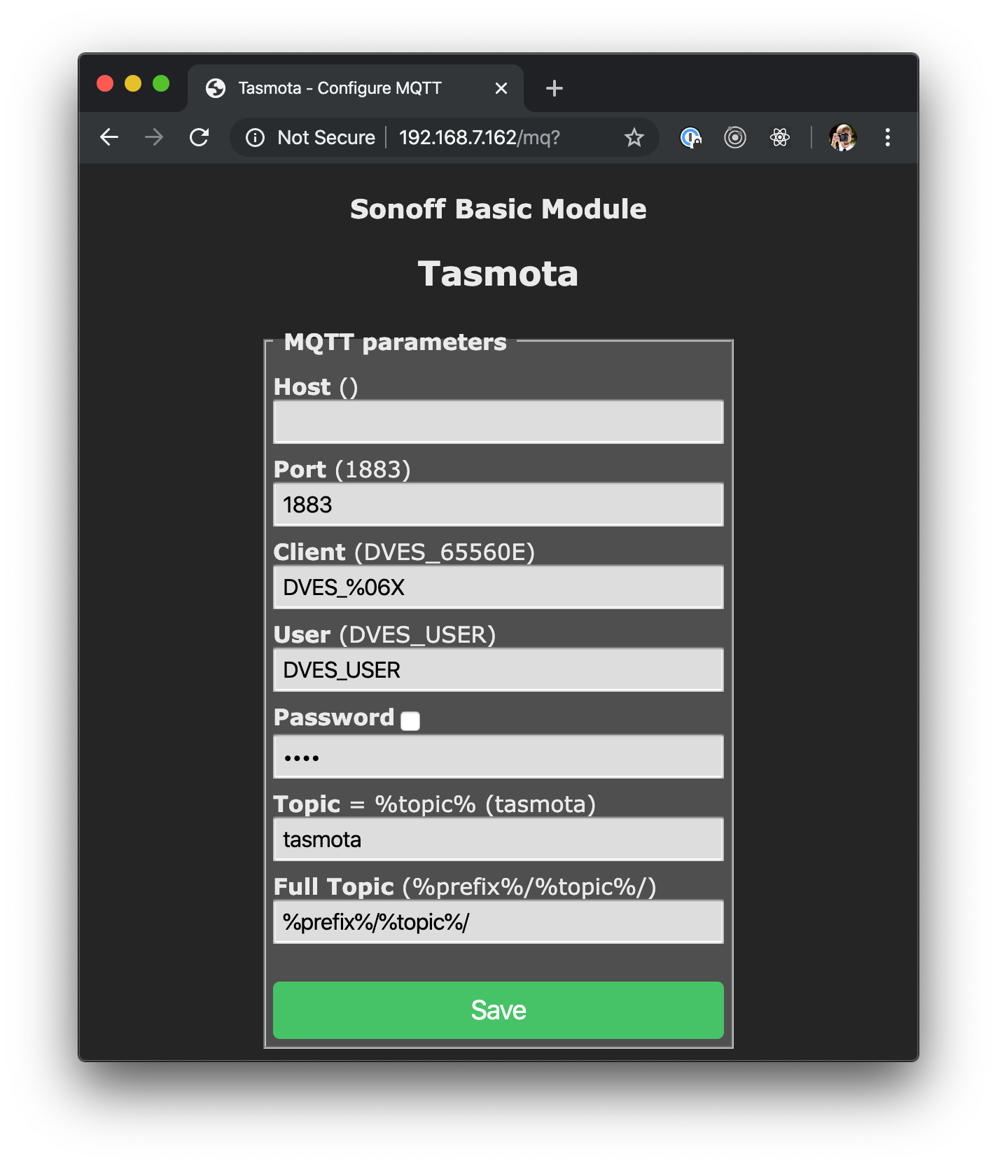
Start by entering in the hostname or ip of your MQTT broker. Optionally a different port, username and password. The topic should be a unique identifier for your R2, so go ahead and change the default of Tasmota to whatever you’d like to name it.
At this point you could simply save and the Sonoff R2 would now be sending and receiving MQTT messages.
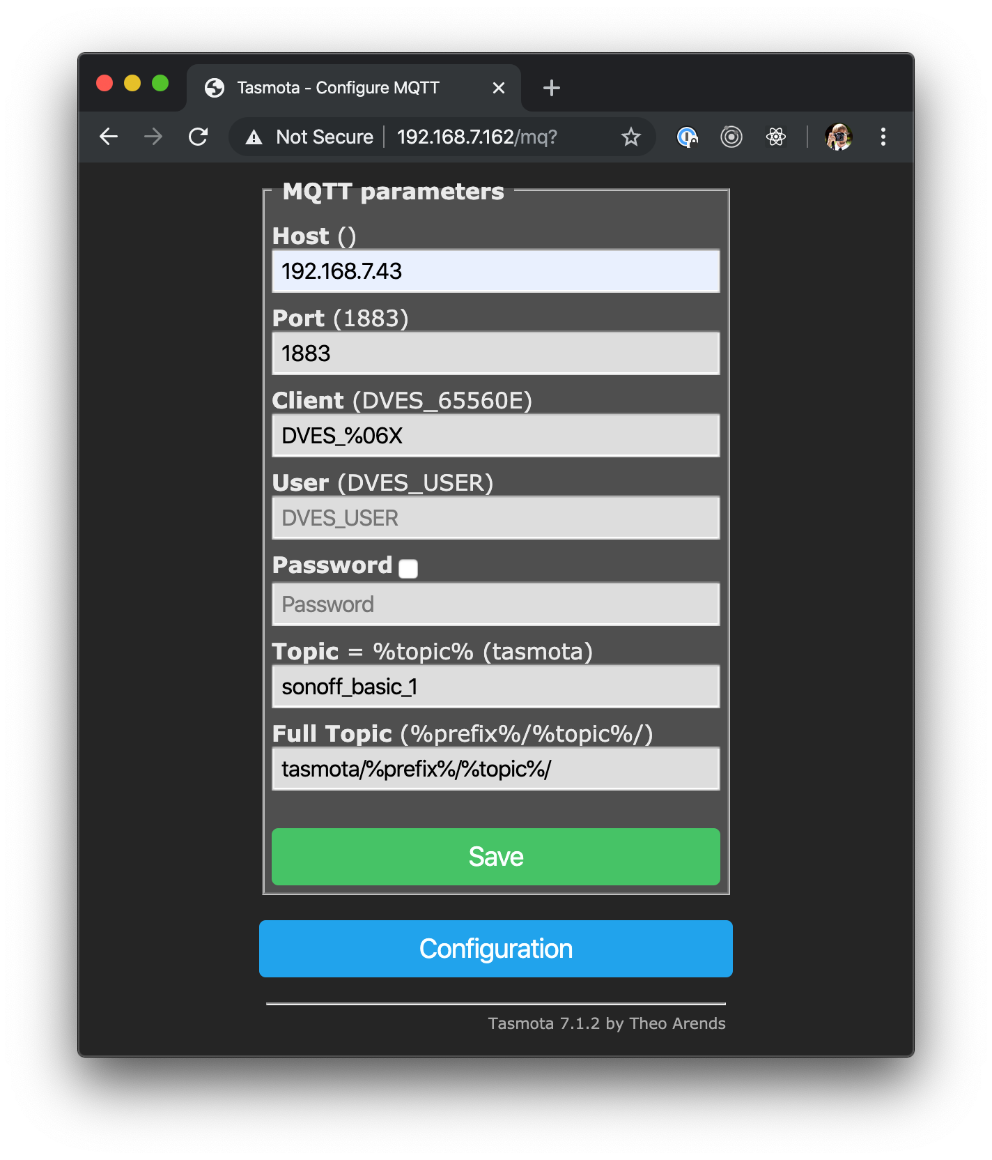
Note: I did make the conscious choice to configure my Tasmota flashed devices manually with Home Assistant and not use the auto discovery feature for no other reason that I wanted complete control and the auto discovery scares me. I also added Tasmota to the beginning of the full topic and all future devices I add will use Tasmota as the root of their topics as well.
What will the topics look like?
You’ve defined your unique %topic% and the %prefix% will be one of 3 things: cmd, stat, and tele. Cmd is for issuing commands or asking for status. Stat will report back status or configuration messages. Tele will report telemetry info.
In my case an example topic would be:
tasmota/stat/sonoff_basicThe payload might look like:
{“POWER”:”ON”}Note: I used MQTTBox to do my testing.
Optional Configuration
I also went into Configuration → Configure Other and changed the Friendly Name to be the same as the Topic name that I configured in MQTT.
The final thing I did was set the PowerRetain option in the console.
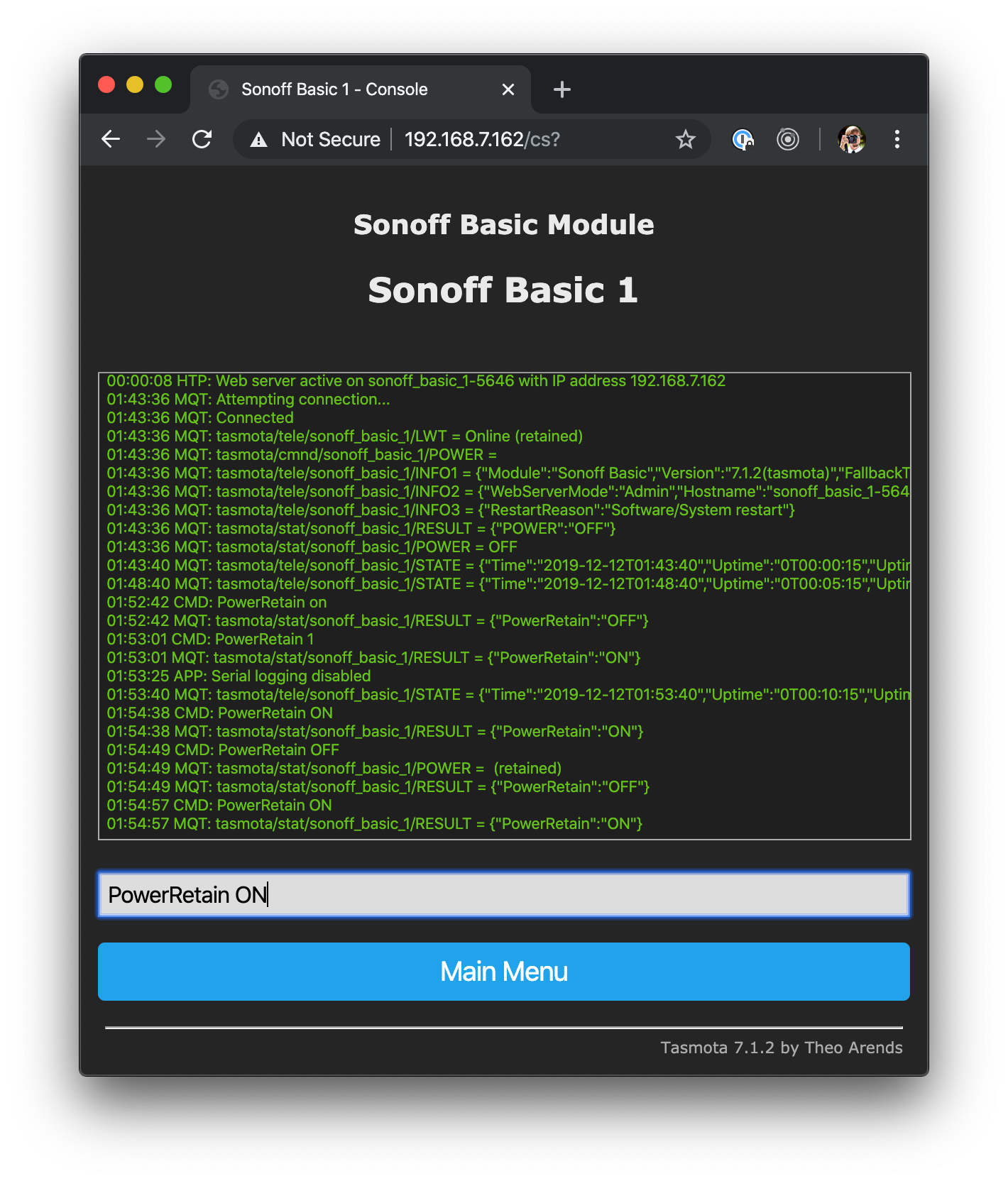
From the main menu click on Console. In the input type “PowerRetain ON” and press return. The state of the power messages will now be retained and anytime something such as Home Assistant connects to the broker they will know the last state of the device.
Putting it Back Together
So, I chose to add the R2 to an extension cord, but you could easily do the same thing to add it directly to the cord of anything you want to plug into an outlet. I used an extension cord since this is going to control my Christmas lights and I’d like to reuse it for other things once Christmas is over.
First go ahead and pop the R2 board back into the plastic enclosure. Set it in the base and snap the top on. The first time I did this I attached the cord before doing this and then realized I had to take the whole thing apart again.
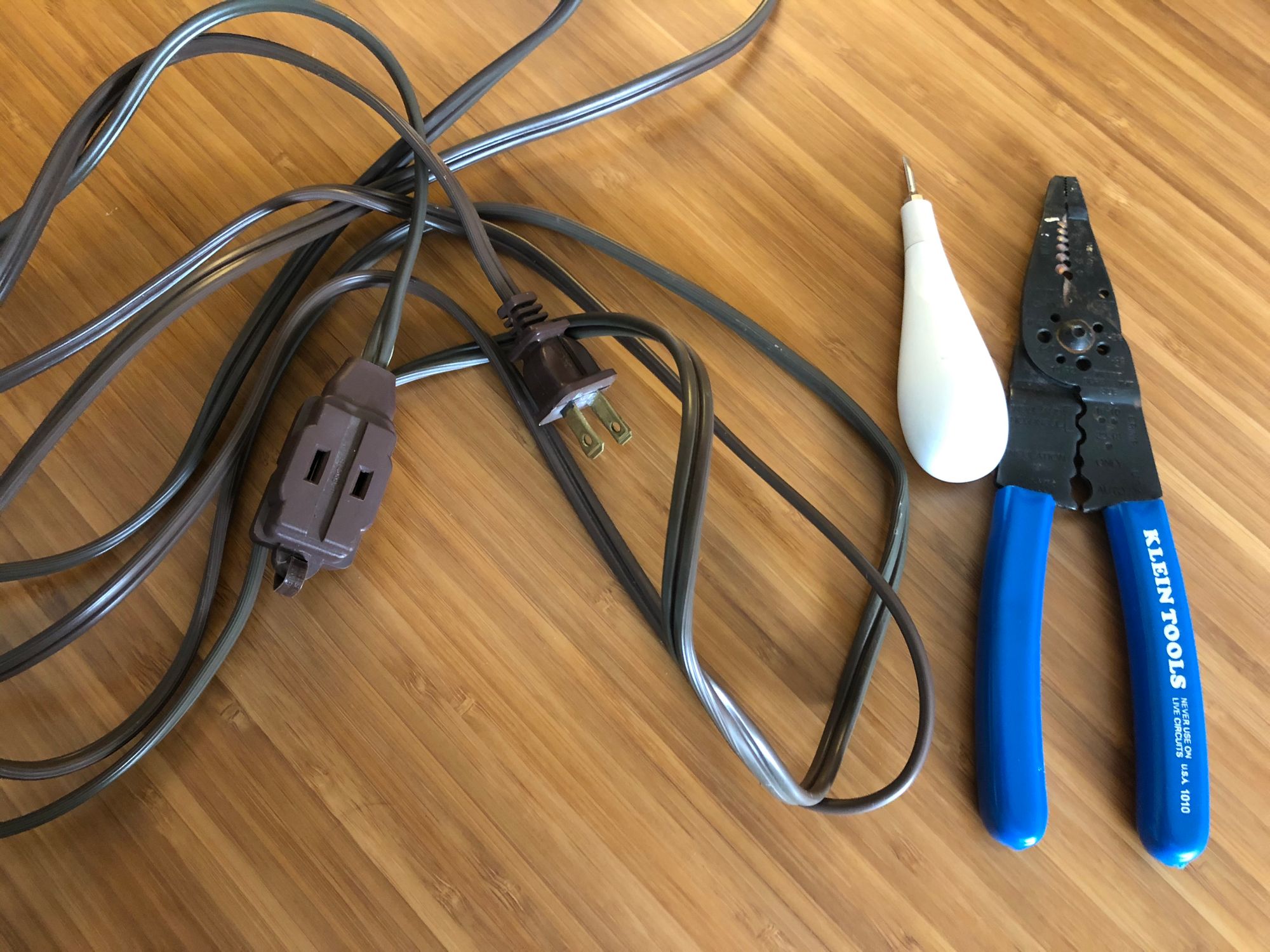
Next let’s get the extension cord ready. You’ll need a wire stripper and a scissors or knife.
Start off by cutting the extension cord. I cut mine near the plug and gave it enough length that the R2 will rest on the ground. You can make the cord whatever length you’d like so if you want a 1 foot cord just cut off the excess.
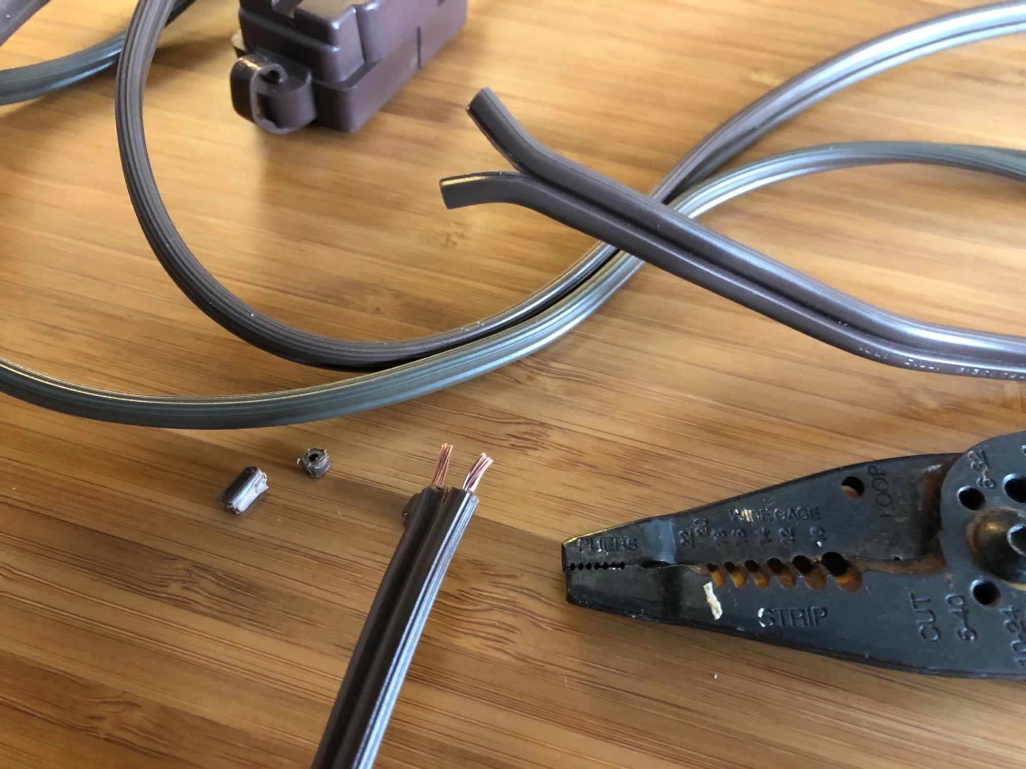
Once you have it cut, take a scissors or knife and cut between the two wires about a half inch or so. Then take the wire stripper and strip about 1/4" off. It really doesn’t need to be much.
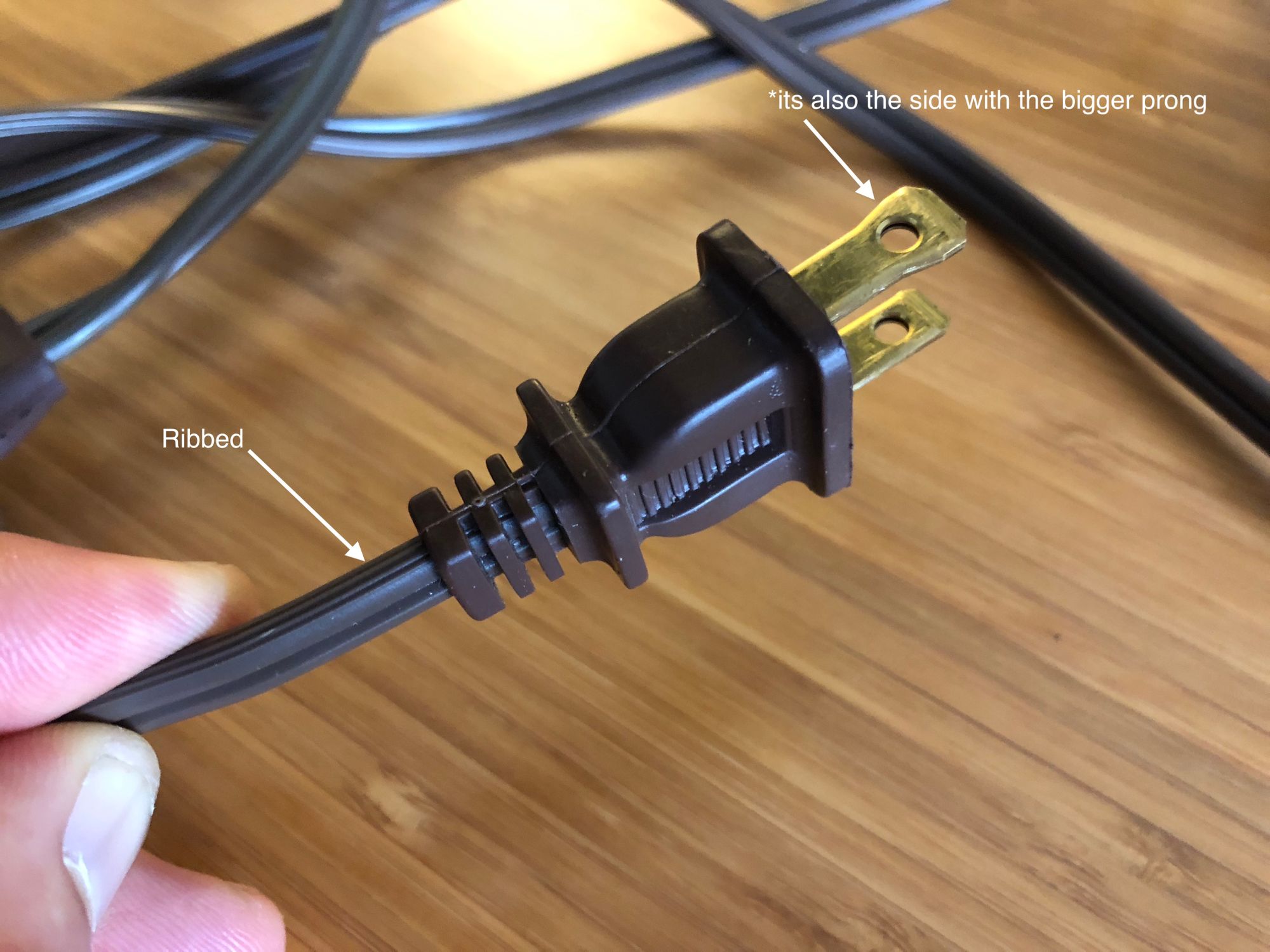
Note: You might be wondering which wire goes in L (load) and which goes in N (neutral). If you look and feel the cord you’ll notice that one side is smooth and one is ribbed or not smooth. The not smooth one will be inserted into N.
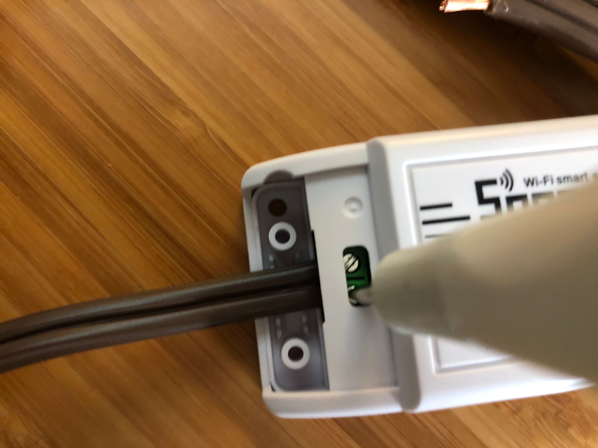
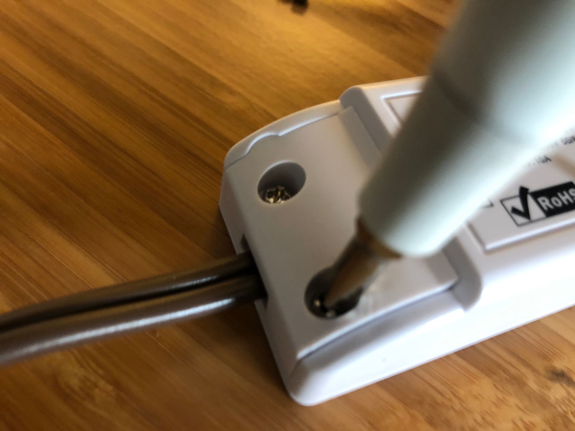
Insert the male end or piece of the cord with the actual plug in the end of the R2 that says Input. Then tighten it down with a small flat head screwdriver.
Ribbed Wire → N
Smooth Wire → L
Do the same with the other end of the extension cord on the Output side of the R2. Once both parts of the cord are secured put the caps on either side and tighten down the screws included in the box with a small phillips screwdriver.
Now go plug it in and you are set to go!
Wrapping Up
These are all the steps for setting up the Sonoff R2 using Tasmota and getting it talking with your MQTT broker. At this point you can integrate and control it however you would like either via its web interface or over MQTT. In another article I’ll show how to manually add these devices to Home Assistant, and setup some basic automations.